Share your ENCOR v1.2 Experience 18 Mar 4:11 PM (yesterday, 4:11 pm)
The new version of the ENCOR v1.2 has come to replace the old ENCOR version so we create the “Share your ENCOR v1.2 Experience” for everyone to share their experience to prepare for this new exam.
Please share with us your experience to prepare for the new version of the ENCOR 350-401 v1.2 exam, your materials, the way you learned, your recommendations… But please DO NOT share any information about the detail of the exam or your personal information, your score, exam date and location, your email…
Note:
+ The ENCOR 350-401 v1.2 exam include lab sims, multiple choice and Drag drop questions.
+ You can use shortcut command (like “int”, “no sh”, “conf t”…), “tab” and “?” in the simulations of the exam.
+ To get the new CCNP Enterprise certificate, you need to pass this ENCOR 350-401 exam (core exam) and one of the
concentration exam.
Your posts are warmly welcome! Hope you will find useful information here!


ENCOR Tutorials & Practice Labs 1 Jul 2025 4:27 PM (8 months ago)
We have many tutorials and practice labs on our site to help you understand the concepts of the ENCOR exam. We have summarized them here in one place and categorized them into specific topics to make your learning easier.
================== ENCOR Tutorials ==================
- SDWAN Architecture Overview (on certprepare.com)
- Point to Point Protocol (PPP) Tutorial
- Gateway Load Balancing Protocol GLBP Tutorial
- Border Gateway Protocol BGP Tutorial
- OSPF LSA Types Tutorial
- Network Address Translation NAT Tutorial (on 9tut.com)
- Network Time Protocol (NTP) Tutorial (on 9tut.com)
- Hot Standby Router Protocol HSRP Tutorial (on 9tut.com)
- EtherChannel Tutorial (on 9tut.com)
- Access List Tutorial (on 9tut.com)
- Control Plane Policing (CoPP) Tutorial (on networktut.com)
- AAA TACACS+ and RADIUS Tutorial (on 9tut.com)
- Connect Python to GNS3 for Automation in Win10
- Python for ENCOR
- Embedded Event Manager (EEM) Tutorial
- REST API Tutorial (on 9tut.com)
- Puppet Tutorial (on 9tut.com)
- Chef Tutorial (on 9tut.com)
- Ansible Tutorial (on 9tut.com)
- JSON Tutorial (on 9tut.com)
================= ENCOR Practice Labs =================
Practice labs help individuals and professionals gain practical experience with networking technologies by configuring routers & switches on the emulators.
- Configure Cisco Router Passwords – GNS3 Lab
- Configure Static Route – GNS3 Lab
- Redistribute EIGRP and OSPF – GNS3 Lab
- BGP next-hop-self, community no-export & send-community – GNS3 Lab
- Use Distribute-list to filter Routing Updates in BGP
- BGP Summary Route
- BGP Route map and MED – GNS3 Lab
- OSPF EIGRP Redistribute Lab
- Auto and Manual Summary Routes to Null0 with EIGRP
- Policy Based Routing Lab
- OSPF LSA Types Lab
- LISP Lab
================= ENCOR Lab Challenges =================
Lab Challenges require you to configure or troubleshooting preconfigured labs.
- Lab 1: https://www.digitaltut.com/interactive_labs/practice/Four_Switches_Lab_1 (about RSTP, trunking mode)
- Lab 2: https://www.digitaltut.com/interactive_labs/practice/Four_Switches_Lab_2 (about MST, Native VLAN)
- Lab 3: https://www.digitaltut.com/interactive_labs/practice/Four_Switches_Lab_3 (about VTP, Spanning-tree features, Local SPAN)
- Lab 4: https://www.digitaltut.com/interactive_labs/practice/Four_Switches_Lab_4 (about Private VLAN – This is not an ENCOR topic so you can ignore it)
- Lab 5: https://www.digitaltut.com/interactive_labs/practice/Four_Switches_Lab_5 (about Port Security)
- Lab 6: https://www.digitaltut.com/interactive_labs/practice/Four_Switches_Lab_6 (about HSRP)
- Lab 7: https://www.digitaltut.com/interactive_labs/practice/Four_Switches_Lab_7 (about AAA Authentication, SNMP, Syslog, RSPAN)
Hypervisor type 1 and 2 Tutorial 11 Apr 2025 7:15 AM (11 months ago)
A virtual machine (VM) is a software emulation of a physical server with an operating system. From an application’s point of view, the VM provides the look and feel of a real physical server, including all its components, such as CPU, memory, and network interface cards (NICs).
A hypervisor, also known as a virtual machine monitor, is a software that creates and manages virtual machines. A hypervisor allows one physical server to support multiple guest VMs by virtually sharing its resources, such as memory and processing.
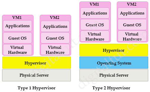
There are two types of hypervisors: type 1 and type 2 hypervisor.
In type 1 hypervisor (or native hypervisor), the hypervisor is installed directly on the physical server. Then instances of an operating system (OS) are installed on the hypervisor. Type 1 hypervisor has direct access to the hardware resources. Therefore they are more efficient than hosted architectures. Some examples of type 1 hypervisor are VMware vSphere/ESXi, Oracle VM Server, KVM and Microsoft Hyper-V.
In contrast to type 1 hypervisor, a type 2 hypervisor (or hosted hypervisor) runs on top of an operating system and not the physical hardware directly. A big advantage of Type 2 hypervisors is that management console software is not required. Examples of type 2 hypervisor are VMware Workstation (which can run on Windows, Mac and Linux) or Microsoft Virtual PC (only runs on Windows).
Comparison Type 1 and Type 2 hypervisors
| Type 1 hypervisor | Type 2 hypervisor | |
| Other name | Bare metal hypervisor | Hosted hypervisor |
| Runs on | Underlying physical host machine hardware | Underlying operating system (host OS) |
| Best suited for | Large, resource-intensive, or fixed-use workloads | Desktop and development environments |
| Can negotiate dedicated resources? | Yes | No |
| Knowledge required | System administrator-level knowledge | Basic user knowledge |
| Examples | VMware ESXi, Microsoft Hyper-V, KVM | Oracle VM VirtualBox, VMware Workstation, Microsoft Virtual PC |
Structure of virtualization in a hypervisor
Hypervisors provide virtual switch (vSwitch) that Virtual Machines (VMs) use to communicate with other VMs on the same host. The vSwitch may also be connected to the host’s physical NIC to allow VMs to get layer 2 access to the outside world.
Each VM is provided with a virtual NIC (vNIC) that is connected to the virtual switch. Multiple vNICs can connect to a single vSwitch, allowing VMs on a physical host to communicate with one another at layer 2 without having to go out to a physical switch.
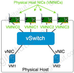
Although vSwitch does not run Spanning-tree protocol but vSwitch implements other loop prevention mechanisms. For example, a frame that enters from one VMNIC is not going to go out of the physical host from a different VMNIC card.
Benefits of Virtualizing
Server virtualization and the use of virtual machines is profoundly changing data center dynamics. Most organizations are struggling with the cost and complexity of hosting multiple physical servers in their data centers. The expansion of the data center, a result of both scale-out server architectures and traditional “one application, one server” sprawl, has created problems in housing, powering, and cooling large numbers of underutilized servers. In addition, IT organizations continue to deal with the traditional cost and operational challenges of matching server resources to organizational needs that seem fickle and ever changing.
Virtual machines can significantly mitigate many of these challenges by enabling multiple application and operating system environments to be hosted on a single physical server while maintaining complete isolation between the guest operating systems and their respective applications. Hence, server virtualization facilitates server consolidation by enabling organizations to exchange a number of underutilized servers for a single highly utilized server running multiple virtual machines.
By consolidating multiple physical servers, organizations can gain several benefits:
+ Underutilized servers can be retired or redeployed.
+ Rack space can be reclaimed.
+ Power and cooling loads can be reduced.
+ New virtual servers can be rapidly deployed.
+ CapEx (higher utilization means fewer servers need to be purchased) and OpEx (few servers means a simpler environment and lower maintenance costs) can be reduced.
Para-virtualization
Para-virtualization is an enhancement of virtualization technology in which a guest operating system (guest OS) is modified prior to installation inside a virtual machine. This allows all guest OS within the system to share resources and successfully collaborate, rather than attempt to emulate an entire hardware environment. The modification also decreases the execution time required to complete operations that can be problematic in virtual environments.
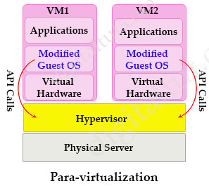
By granting the guest OS access to the underlying hardware, Para-virtualization enables communication between the guest OS and the hypervisor (using API calls), thus improving performance and efficiency within the system. This is the main difference between Para-virtualization and (traditional) full-virtualization.
Connect Python to GNS3 for Automation in Win10 23 Feb 2024 2:50 PM (2 years ago)
In this lab we will learn how to program Python (version 3) to telnet to GNS3 router in Windows 10 and do some configuration commands like create an interface on GNS3 router.
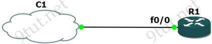
Our topology is very simple with only R1 router and a cloud (represented our real laptop/desktop). But please do not create a cloud now as we need to configure a Microsoft Loopback Adapter for it first so please follow the steps below.
1. Install the “KM-TEST Loopback Adapter” in Win10
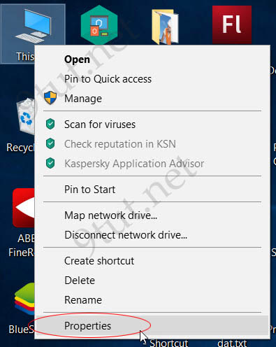
Right-click on “My Computer” choose “Properties”.
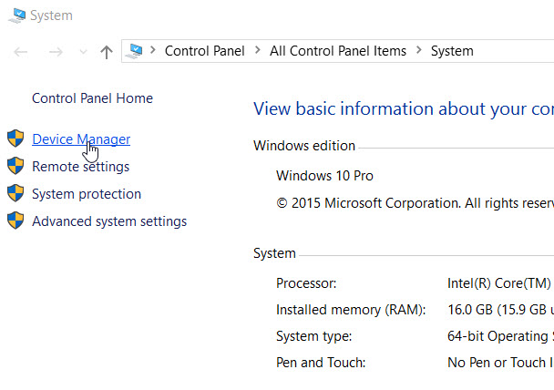
Under “System” dialog choose “Device Manager”
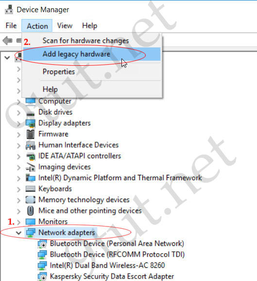
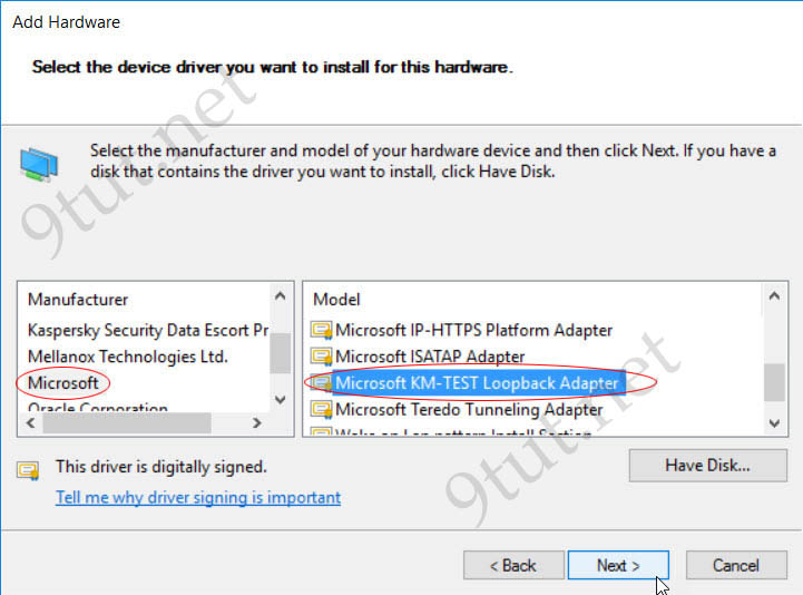
Under “Device Manager” dialog choose “Network Adapters” then click on “Action” menu and choose “Add legacy hardware”.
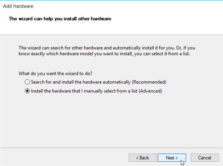
Choose “Install the hardware that I manually selection from a list” option
Wait for a moment so that Windows loads a list of driver. Then we choose “Microsoft” under “Manufacturer” list and choose “Microsoft KM-TEST Loopback Adapter” under “Model” list:
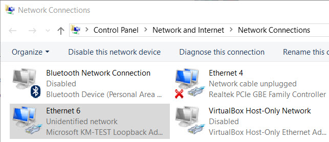
Wait for a moment so that Windows can install this loopback adapter for you. Now open Control Panel > Network and Sharing Center > Change adapter settings we will see a new interface has been installed.
In the next part we will assign an IPv4 address to our new loopback interface.
2. Configure our router with IP address of 10.1.1.1/24 on the interface that is connected to our cloud.
Now we can open GNS3 and create a topology that we posted earlier:
Open R1 and configure it as follows:
Configuration on R1:
| R1#configure terminal R1(config)#username R1 password 12345 R1(config)#enable secret cisco R1(config)#interface FastEthernet0/0 R1(config-if)# ip address 10.1.1.1 255.255.255.0 R1(config-if)# no shut R1(config-if)#line vty 0 4 R1(config-line)#login local |
We have just created an username and password for the telnet lines and create a secret password of “cisco” to enter privileged mode before doing some configuration. Notice that the last line “login local” instructs our router to use the local username/password for authentication on VTY (telnet) lines.